
iCamBody Markers
Precision reference bodies placed over multi-unit abutments — the targets the iCam4D scanner reads to map implant positions.

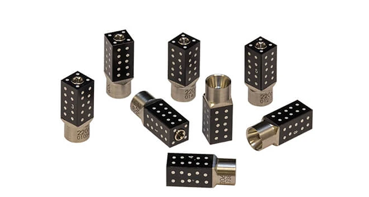
What are iCamBody markers?
iCamBody components are small, precisely machined reference objects that seat over the multi-unit abutments in the patient's mouth. Each body carries a unique pattern of white reference dots on its black faces — patterns the iCam4D photogrammetry system recognizes from any angle.
During capture, the iCam4D scanner photographs the iCamBodies from multiple positions. The software triangulates each marker's exact 3D position, producing an implant-level digital model with sub-10µm accuracy — far beyond what intraoral scanning alone can achieve.
Seats on Multi-Units
Placed directly over abutments in the mouth.
Unique Dot Patterns
Each body is individually identifiable.
Placement in the mouth
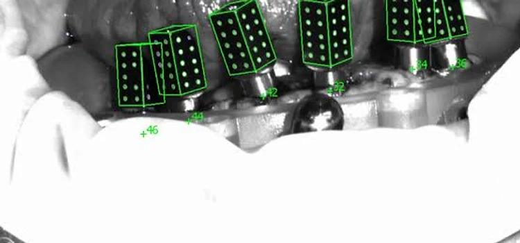
iCamBody markers are placed over the multi-unit abutments just before the iCam4D capture, ensuring every implant position is mapped with micron-level precision.

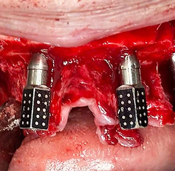
Intraoral Placement
Each iCamBody is seated directly over a multi-unit abutment during surgery. The black cuboid tops with white reference dots remain visible above the tissue, giving the iCam4D scanner clear targets to photograph from multiple angles.

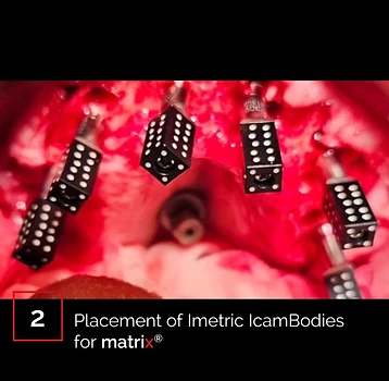
Verified Positioning
The markers are arranged along the arch following the implant distribution. Once all bodies are seated and stable, the iCam4D scanner captures the full field — each marker's unique dot pattern is recognized independently by the software.
Seat the markers
Each iCamBody is placed over a multi-unit abutment, seated flush and stable.
Verify visibility
Ensure all marker faces are visible from multiple angles — no soft tissue covering the dot patterns.
Capture with iCam4D
The scanner photographs the markers from several positions around the arch.
Remove & proceed
Markers are removed. The software computes exact implant positions for your restoration design.

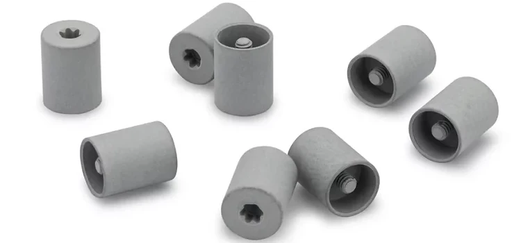
Healing Caps & Tissue Scan
After the iCamBodies are removed, healing caps are placed over the abutments. A separate intraoral scan of the tissue with these healing caps in place is required to align the photogrammetry file to the soft tissue model.
This tissue scan captures the gingival contours and the healing cap positions. The software then uses the known geometry of the healing caps to register the photogrammetry implant data against the soft tissue scan — creating a single, unified digital model where implant positions and tissue contours are perfectly aligned.
Healing caps placed after iCamBody removal
Tissue scan captured with healing caps in situ
Software aligns photogrammetry data to tissue model
Software Recognition
When the tissue scan is imported, the software automatically identifies each healing cap and iCamBody position. The system reports the number of bodies detected, the views captured, and the exposure values — ensuring the data is complete before alignment.
Each recognized marker is labeled with its corresponding implant position, creating a mapped dataset that can be registered against the photogrammetry file.

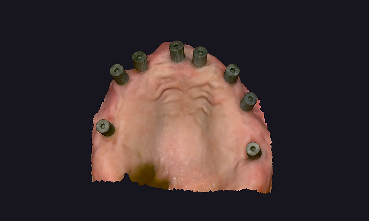
Tissue Scan with Healing Abutments
A 3D scan of the soft tissue with healing abutments in place — the reference model that the photogrammetry file is aligned to.


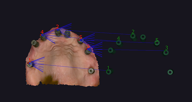
Aligning Photogrammetry to Tissue
The alignment process bridges two datasets: the photogrammetry file (precise implant positions) and the tissue scan (soft tissue contours with healing caps). The software identifies corresponding reference points in both models — the healing cap positions in the tissue scan map directly to the implant positions in the photogrammetry file.
Virtual connections are drawn between matching points, and the software calculates the optimal alignment transformation. The result is a single composite model where implant positions and tissue contours are perfectly registered — ready for full-arch restoration design.
Corresponding reference points identified in both datasets
Point-to-point registration calculates optimal alignment
Composite model merges implant precision with soft tissue contours